well folks, started the rewire and will add the stages as and when I complete them. If I do it this way, I can remember what I did rather than trust my crap memory.
this is without starter, indicators and with an ignition relocation.
Plan
This is the most important stage of any rewire, plan! boring I know, but absolutley necessary.
first make sure you have all the bits on your bike, no good if the engine is in london and the frame in holland. get it built!
1. make out a shopping list in excel, what size of wire, how long and what is its job and how is it going to be protected from the elements and will it look good too?
I use vehicle wiring products for everything, saves on postage. this stage took 3 weeks to do. there are 2 types of wire, the older stuff which is thicker per amp rating and the thinwall stuff which, as the name suggests, has a high performance PVC insulation so making the wires thinner, thus lighter and easier to hide!
to work out what you need size wise you calculate watts divide by Volts = amps, don't forget that volts can drop on a bike so I allowed 10volts in the calculation as a buffer.
after sizes you need to keep to a colour scheme. The original one is the best and will help to identify and problem solve further on in the rewire. There are also tracer wires which, when 2 colours are given, the first is the main colour and the second is the tracer or coloured line of the wire.
2. layout
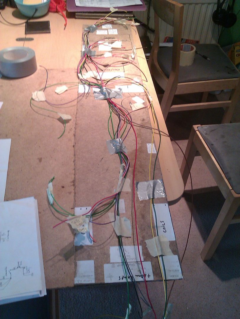
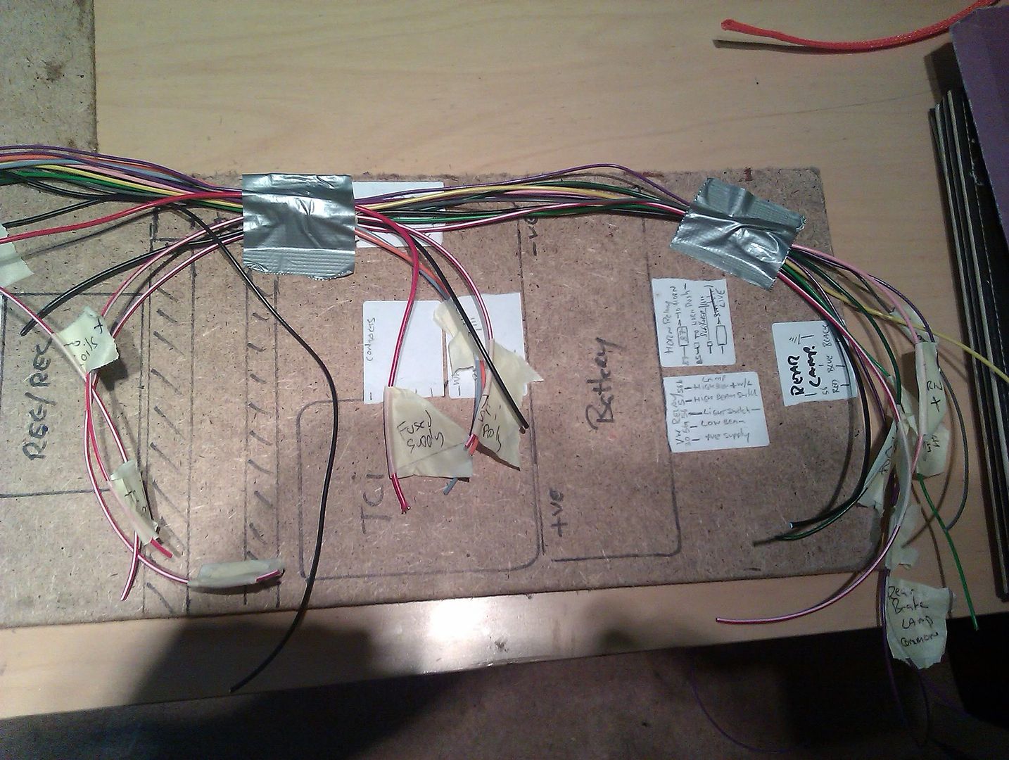
you need a layout of the proposed wiring loom and the best way to do that is make a layout board.
this gives the length and width of the bike's frame and allows you to visualise the layout and route of your proposed wiring.
here's mine;
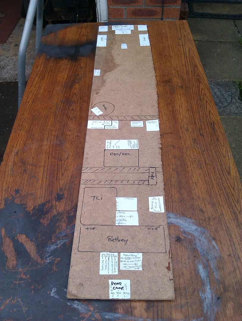
i stuck labels on the board indicating the actual device to be wired and any obstructions there. That way the length of wire can be calculated more acuratley.
If anything is lower or higher or wider than the board, I add a label , say what the device is and write + 80mm for example!
first componant
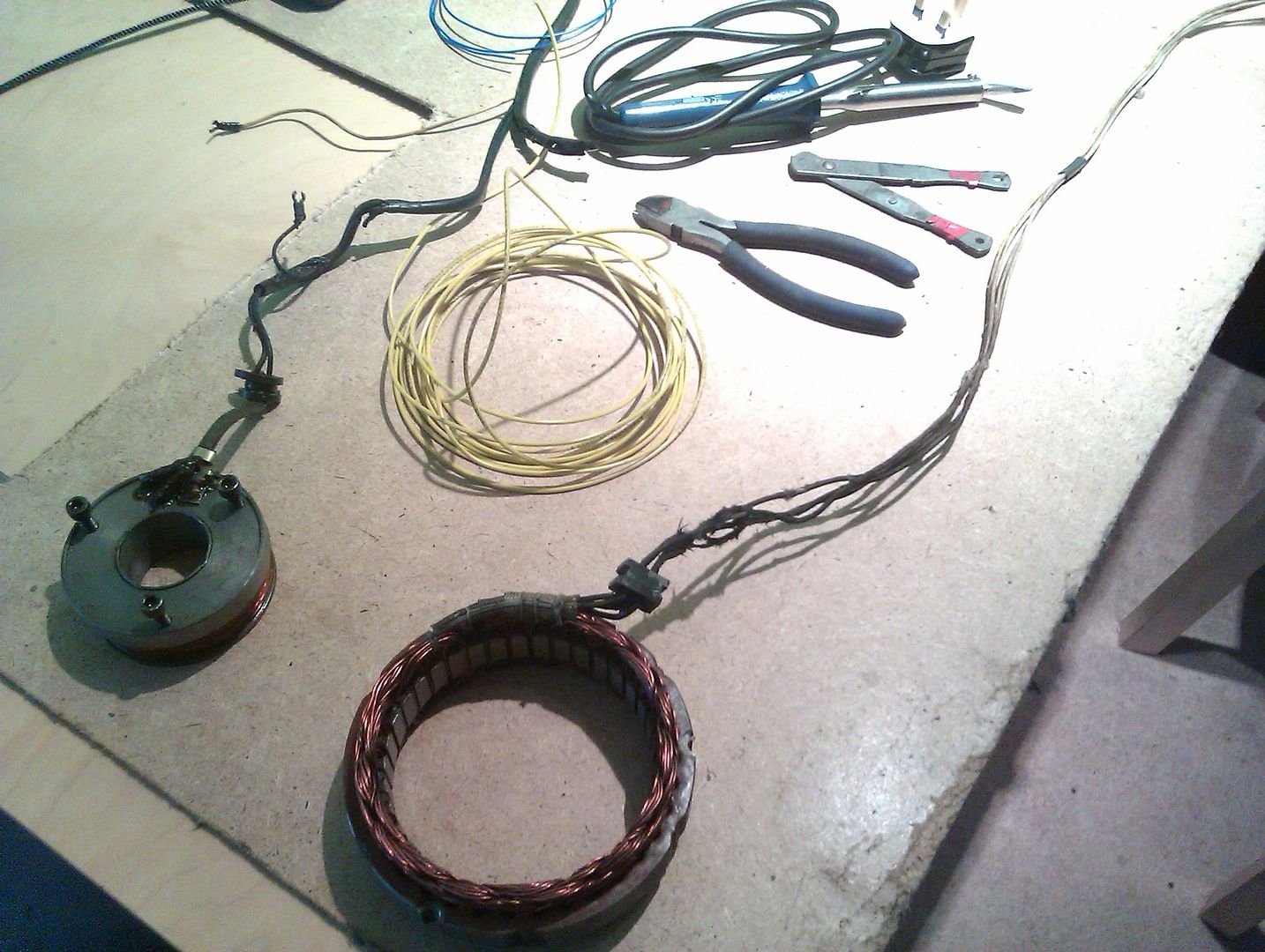
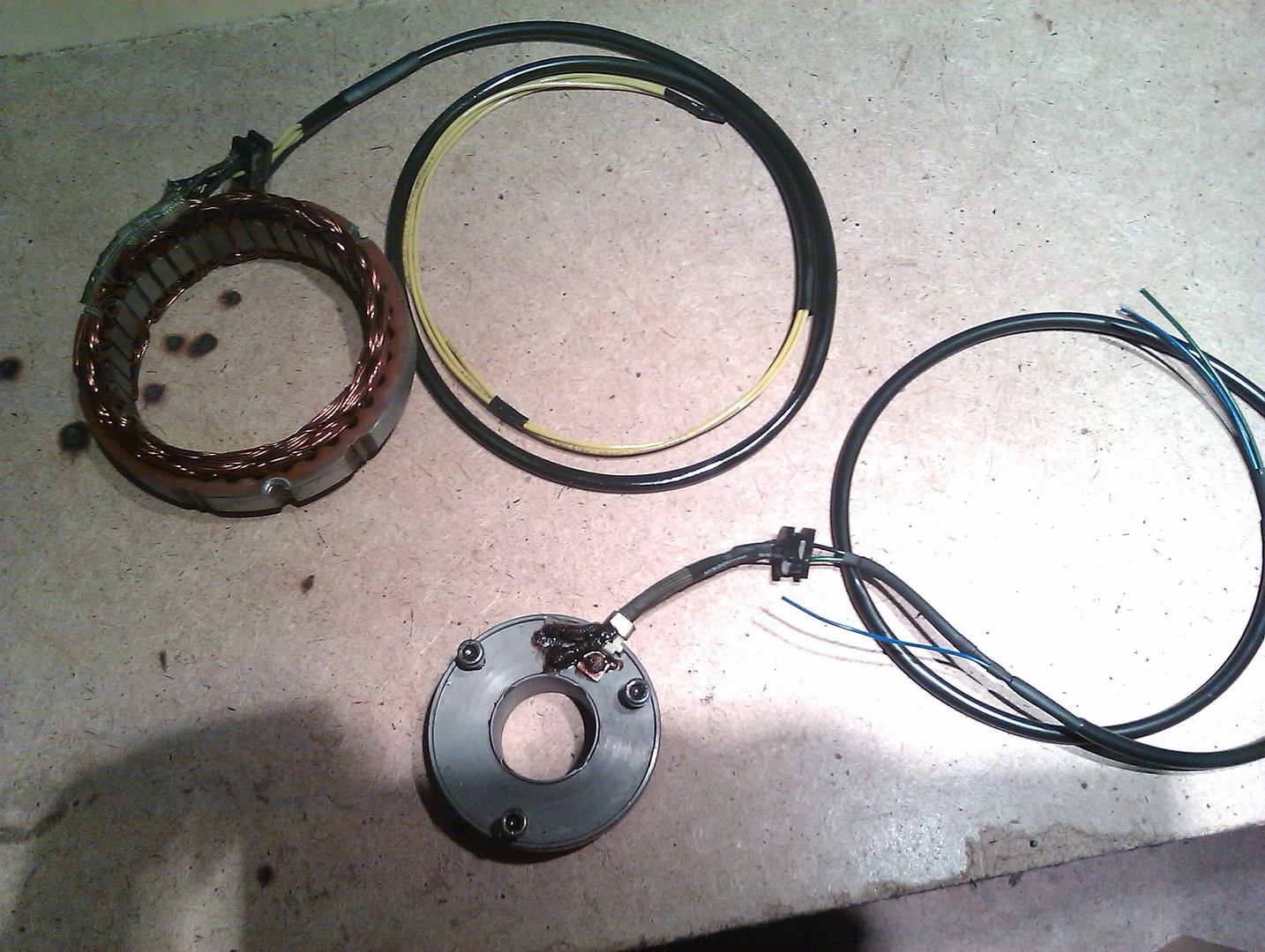
I started with the alternator wiring first, I think its the trickier part of wiring and its full of oily mess etc.
first things first, you need tools
wire snips, some insulating tape, scissors, soldering iron with solder and flux, heat gun for shrink sleeves and wire strippers.
after measuring what I needed, I used yellow tinned thinwall in 1.5mm which equals 21 amps. its more or less the same as the original, but tinned wall is soldered right along the whole length of the wire and is inpervious to water and oil etc so it should last in the environment near that front sprocket!

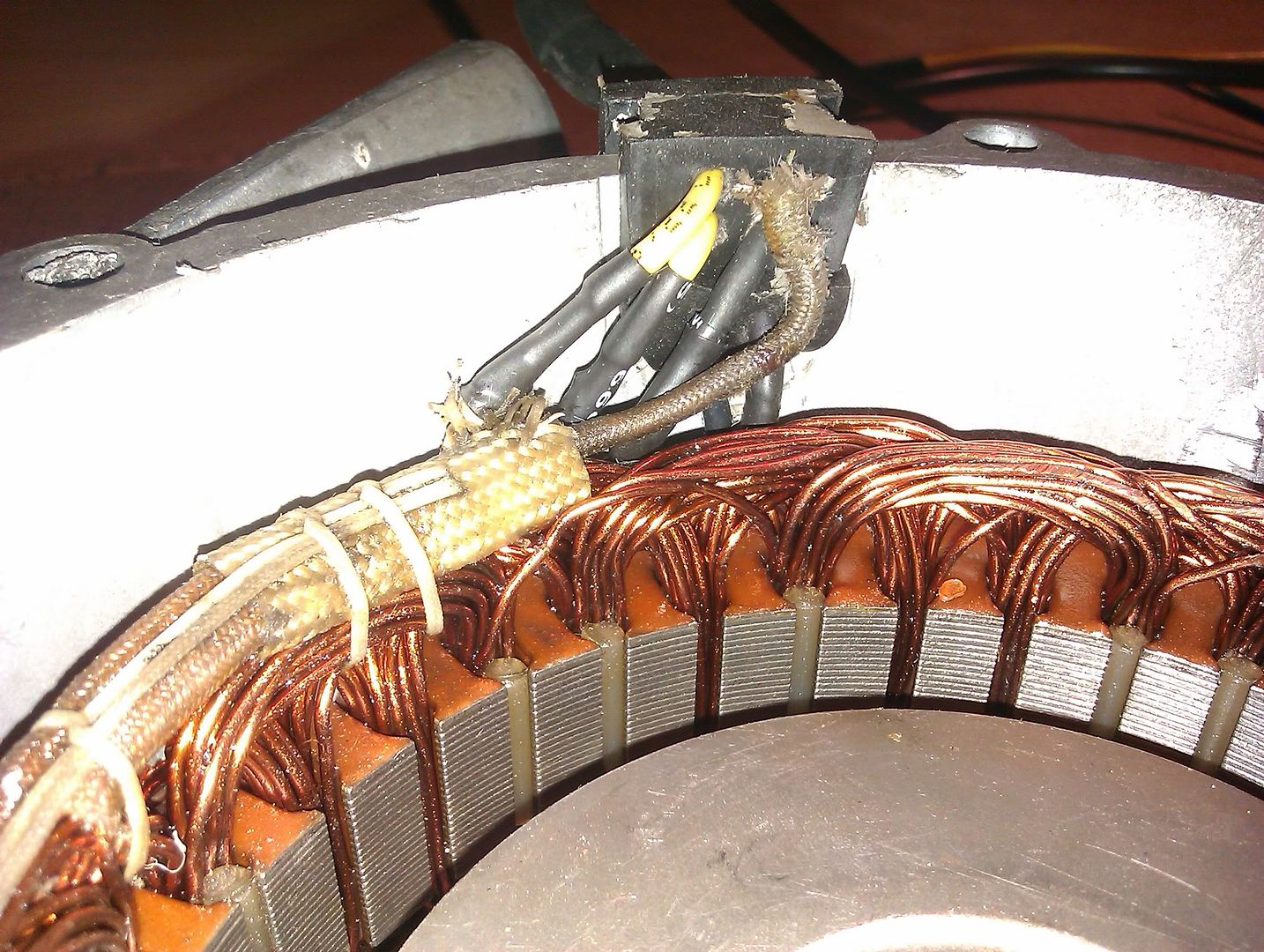
I started on the stator first. i snipped the wires and degreased using some carb cleaner I had lying around. the wires go through the rubber grommet then you thread on a piece of shrink wrap.
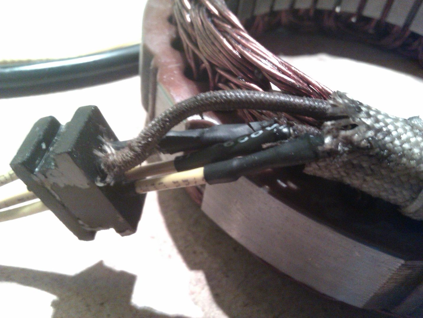
I then fluxed both ends and splayed them out a bit ( you don't want to join it side to side as there isn't much room nestling in the cover) the ends were brought together and solder applied.
I did this for 3 connections, the 4th one is redundant so i just cut it and added a shrink tape on end to leave it terminating within the grommet.
did the field coil the same way as the stator.
this picture shows the stator in the cover and you can see why i needed to make sure the wires didn't over lap
the finished article.
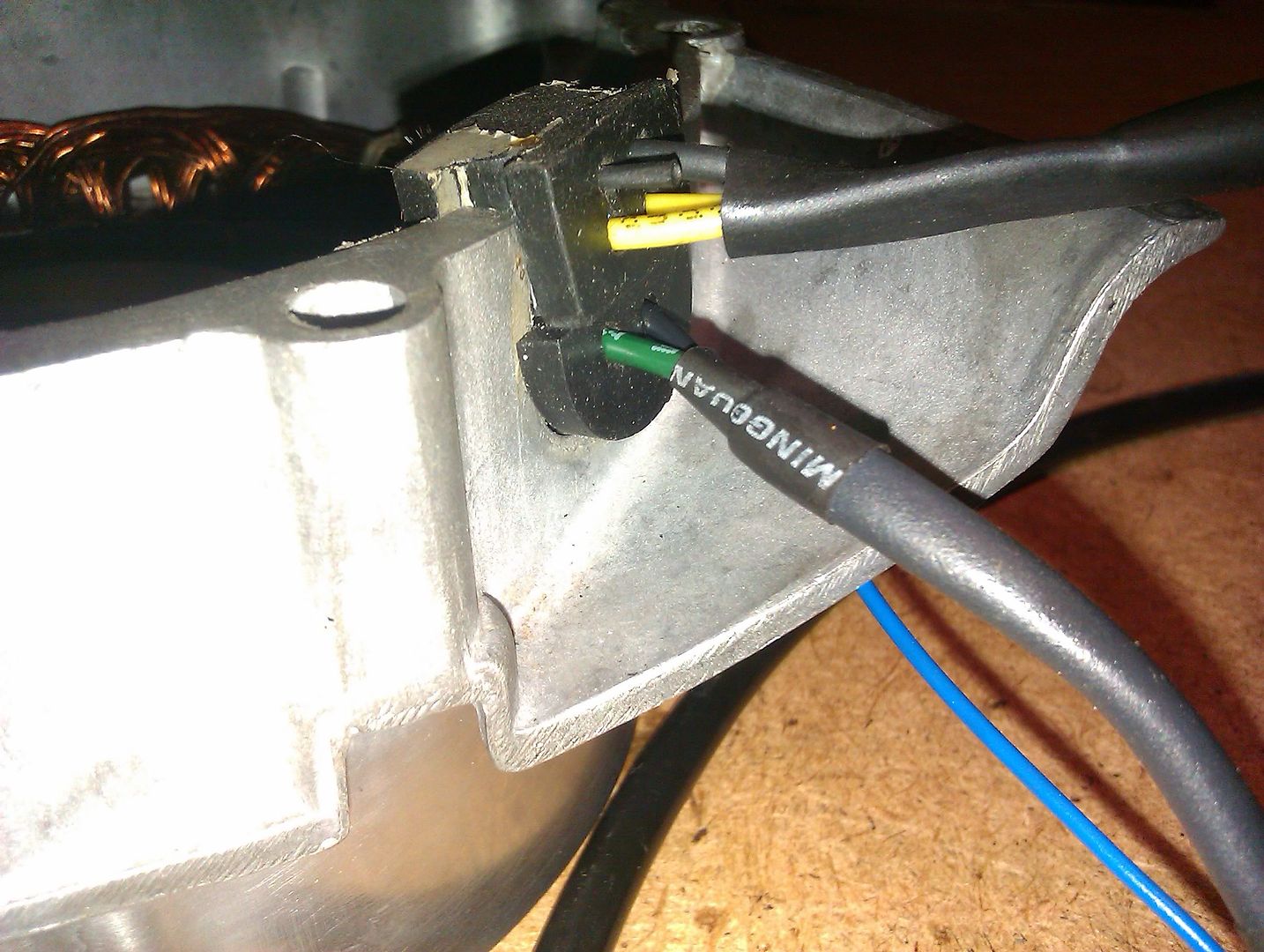
the neutral wire was measured from the field coil as per original and I used shrink wrap and PVC tubing, both before and after the neutral wire.
when you get long length of wires, every 500mm just put a bit of insulating tape there to stop a tangled mess. I used PVC covering on these with shrink tape on each end to stop any ingress of water etc.
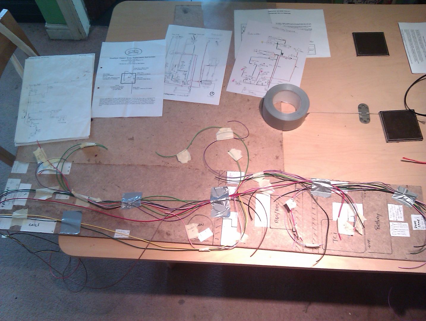
the next stage is to get out your notes, wiring diagram and some masking tape.
for this stage you need to work modular, which means you take each componant separately or your head will spin

I did the longest wires first and decided on the routes they will take.
For my rewire, the lighting system is going down the left side, the ignition, brake wires and earth lead down the middle. This way, if I have any issues at least I only need to tear into one part of the loom and not compromise all of it.
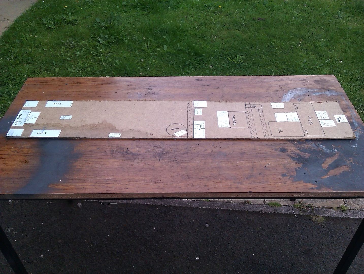
Here are some pictures of wires on the layout board, don't forget work on each component at a time.
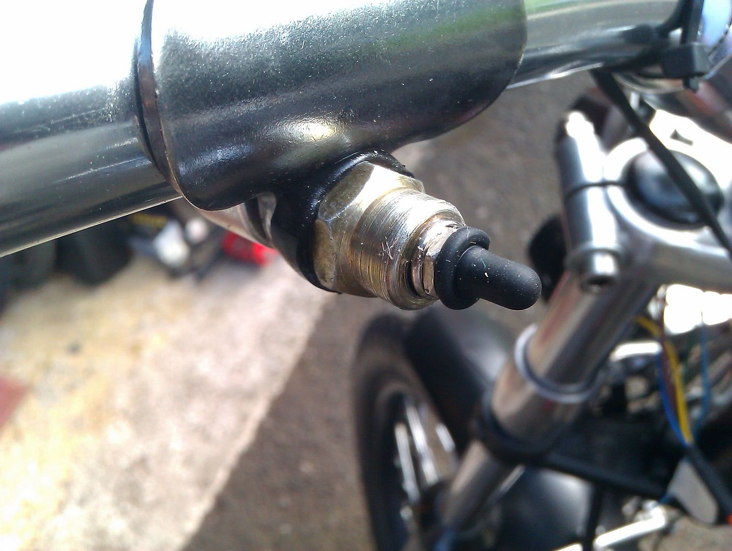
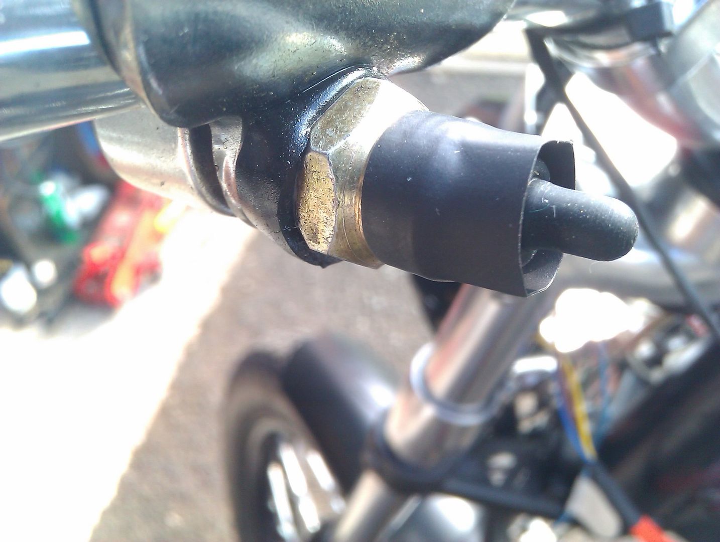
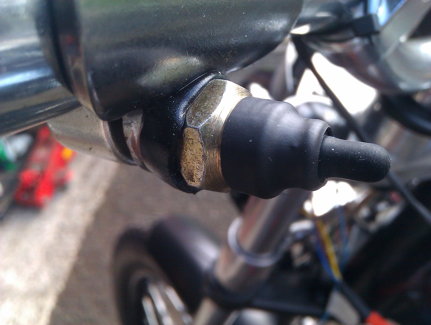
I came to realise early on that the main lamp switch will be carrying some amps and this wasn't anticipated!
The relays will use the switching part only on low amp cable.
I need to get 1.5 mm tinned thinwall (21 amps) for the main switch!

I first use masking tape to layout the wiring and used the same to write on each wire end what's it for, where's it come from. for example; live feed to brake switch.
wrap the wires as you go, masking tape is easy to tear so you can undo/redo as many times as you need.
where a wire leaves the loom, wrap masking tape there, eventually I will use a strip of insulation tape to secure this.
don't put any connections on at all!!
you will need to
1. double check that the loom fits the bike (phsyically check it)
2. PVC wrap or tubing needs to go on in small lengths due to wires exiting along the loom
3. don't forget to put heatshrink tubing on too
a few more pikkies of the board
 frame fit
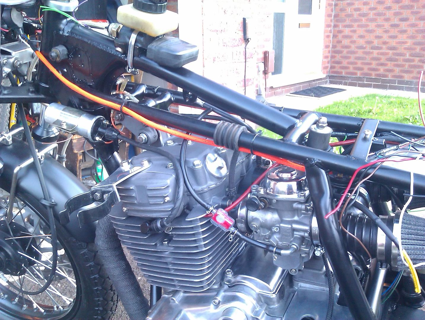
finally got the extra cable and completed the loom layout. The next job is to offer the bare loom to the frame to make sure that the wire breakouts are at the correct position and it fits.
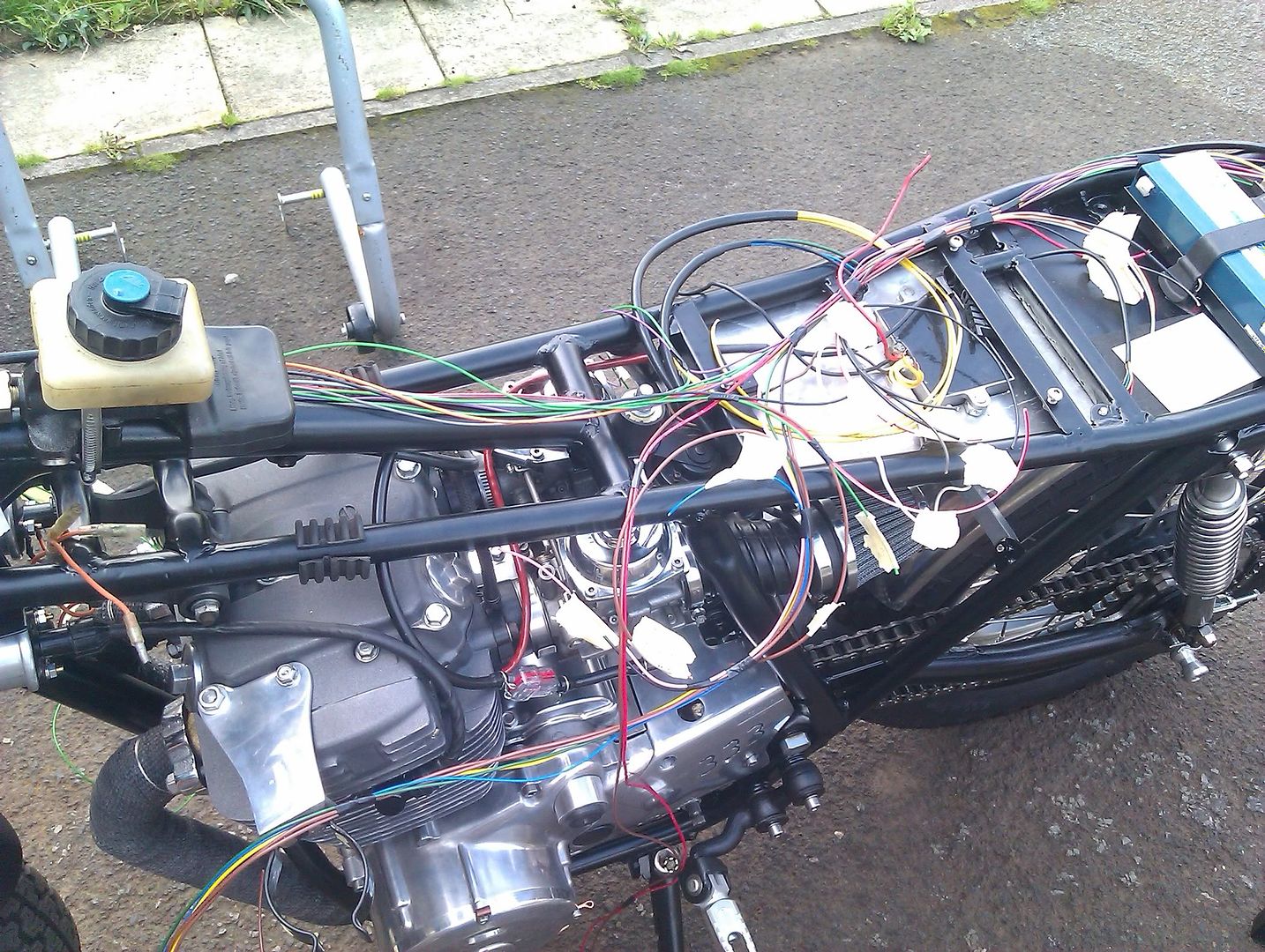
after checking the route and layout on the frame, I marked any changes by using the insulating tape on each breakout and significant change on the loom, EG the start of braid.
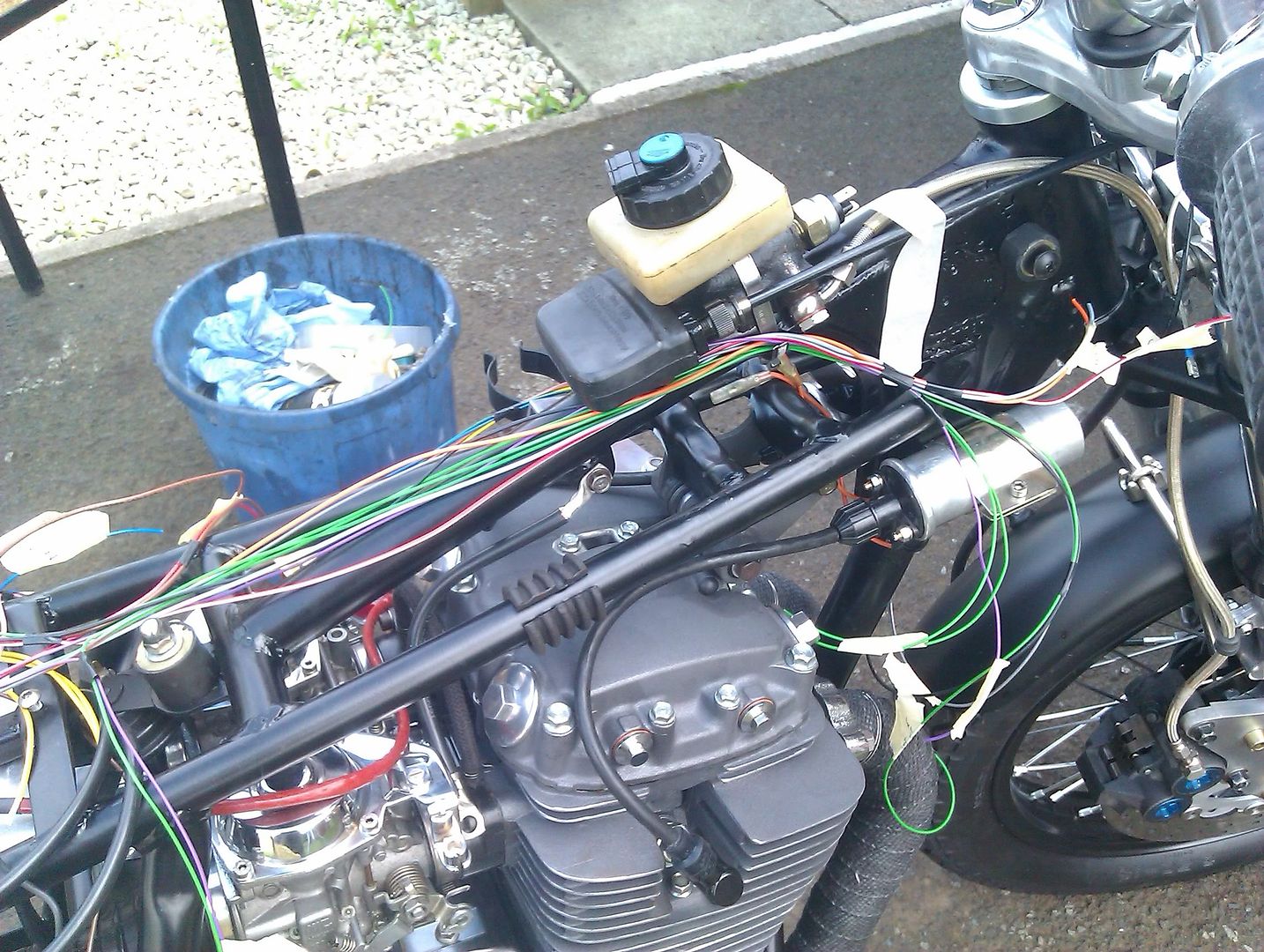
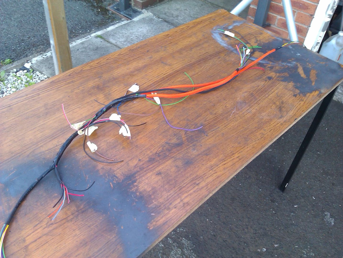
bring the loom back indoors and now this was the hardest part of the rewire!
accept you will cock this bit up, I spent all day threading PVC tube over the wires, only to realise that I should have put heatshrink tubing on or tape.
start from the middle of the loom outwards
there will be places where you cannot put any tubing on, and this is where you use the non adhesive PVC tape.
Start this from the middle outwards as the wires become taught and some start to ride up. Don't worry about this as all you have to do is undo the insulating tape at the end and rebunch the wires together! (that's if you started from the middle of the loom)
wrap the tape really tight and it will look the dogs, finish off with some heat shrink tubing at the end.
Be really patient with this and take your time, have regular breaks etc.
hope fully it will look something like this
Looks like nothing doesn't it?
It bleeding took 4 hours to do

still the eye is in the detail and I well chuffed it turned out as I hoped
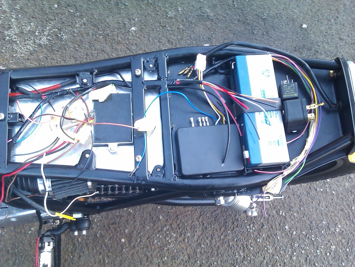
next job is to connect all the components with bullets, spades and solder!